Creating a Geometric Tolerance
You can use the Tolerance command to insert geometric tolerances such as shape and position tolerances in the drawing.
How to create a geometric tolerance:
- Click on Dimension > Tolerance
 on the Ribbon.
or
- Enter TOLERANCE in the command window.
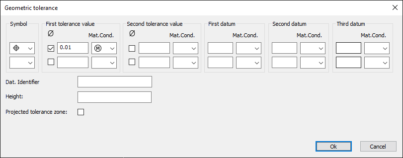
- Select the geometric tolerance symbol.
- a) Enter the tolerance value(s).
b) Activate the diameter symbol (optional).
c) Select an symbol for the material condition (optional). - Enter a Datum identifier (optional).
- Enter a value for the Height (optional).
- Activate the Projected Tolerance Zone symbol (optional).
Geometric tolerance symbols
|
Symbol |
Meaning |
|
|
Position |
|
|
Concentricity or coaxiality |
|
|
Symmetry |
|
|
Parallelism |
|
|
Perpendicularity |
|
|
Angularity |
|
|
Cylindricity |
|
|
Flatness |
|
|
Circularity or roundness |
|
|
Straightness |
|
|
Profile of a surface |
|
|
Profile of a line |
|
|
Circular runout |
|
|
Total runout |


Material condition symbols
|
Symbol |
Meaning |
|
|
At maximum material condition |
|
|
At least material condition |
|
|
Material condition within specified limits |


